Modding: Putting an ATX system into a Apple PowerMac G5 Case - Mark III
Well, it has been a few years and once again I am looking at making changes to my G5 mod. Despite the worry that having a DIY liquid cooled system would be nothing but a string of leaks, short circuits, failures and headaches, the system has actually been very reliable. Even when I moved home, I had no issues with leaks (you just have to remember to keep the system level and not to invert it while moving!).
I can also say that it did a bang up job with the cooling. I drove this workstation hard, even when I personally wasn't running any GPU/CPU intensive code on it I ran BOINC@HOME so that the machine was never idle. The GPU and CPU was pretty much at near 100% utilisation for the entire time the machine was powered on, which for a long time was 24/7. This is because I had "economy 7" overnight electricity, which was much cheaper than normal rates, so I let it churn data when I didn't need it. Over all these years, even in the peak of summer heat, the temperature of the GPU and CPU did not rise beyond 70°C
So if it works so well, why do a "Mark III" version after all these years? Well it has less to do with the system and more to do with the changes in my usage. Originally the system had a GPU card used for CUDA, and this took a lot of power and generated a lot of heat. Likewise the system was my main workhorse, I did all the processing on it, so the CPUs were also driven hard creating more heat. Heat that was most efficient to remove quietly using liquid cooling, so that is what I used.
However now it is 2019, and one big change is that I upgraded my file server with a far more powerful dual 6 core CPU set up (12 cores total!) and installed a CUDA capable card in it, so now it is a processing machine as well. Nowadays I fire off jobs via SSH and let the server do the processing somewhere away from my living space. The result is that my workstation no longer has a powerful GPU card for CUDA work and it spends most of its time idle. In this usage pattern the noise from the pump and cooling system is actually higher than if it was air cooled, plus the cooling system is heavily underutilised. It is effectively overkill for how the system is now used.
In addition I found a flaw in my original design. I did not include any form of dust filters on the intake side. This is a tower PC, so it is always running on or near the floor. In its "Mark II" incarnation loads of dust would get in over time, clog the fans, the radiator fins and leave a coating of dust on all the components inside. This meant that as time went on the system temps would creep up as the radiator and fans got increasingly clogged.
As such this required regular maintenance/servicing of the machine (roughly every 6 months), involving me unplugging everything, taking the machine outside, and blasting out the dust with compressed air then going over everything with brushes followed by a final vacuum.
This regular service was a good thing, because I found that slowly the cooling liquid would evaporate with use, so I would take this moment to top up the coolant as well. Doing this regular service was fine when this was my main processing PC and I needed top notch liquid cooling, but doing it for a system where it is not needed for its current usage pattern was just a waste of time.
It was especially annoying to have to un-plug and re-plug everything (especially re-plugging, as that was much more fiddly to do) as the motherboard was inboard of the case, so I had to thread the cables and connectors through the PCI slots, then twist my fingers in all kinds of odd positions to plug things where they are supposed to go.
So I've decided to make a new version with new goals to reflect new requirements, as well as improvements to things I discovered in the last few years of usage. I am keeping the Apple case, because to date I still think it is one of the prettiest computer cases designed, and it still looks good all these years later. Plus I've not seen any other case built so well with such thick Aluminium. Onwards to the new goals!
Goals
- So one big change, I am not so interested in keeping the case looking "stock". At least where the rear is concerned I don't mind modifying the case to make my life easier when plugging things in.
- Quieter cooling. With the removal of the GPU and most of the processing load being shifted to my server, the cooling system is overkill. The goal now is air cooling, with quietness being the primary goal rather than needing to shift a lot of heat.
- Fitment of dust filters on the intake, for reasons mentioned above
- A general focus on end-user usability and refinement
First stage: Making the case ATX compatible
As already mentioned one of the reasons I moved away from keeping the entire case externally look original is that I found it a headache to plug things in. Additionally it made the whole thing look messy and the motherboard was not mounted securely enough for my liking. Plus having the motherboard further into the case took up a lot of internal space, meaning we had to compromise and put the HDD where the DVD drive should have been (and the DVD drive in my case, was in an external Firewire enclosure instead).
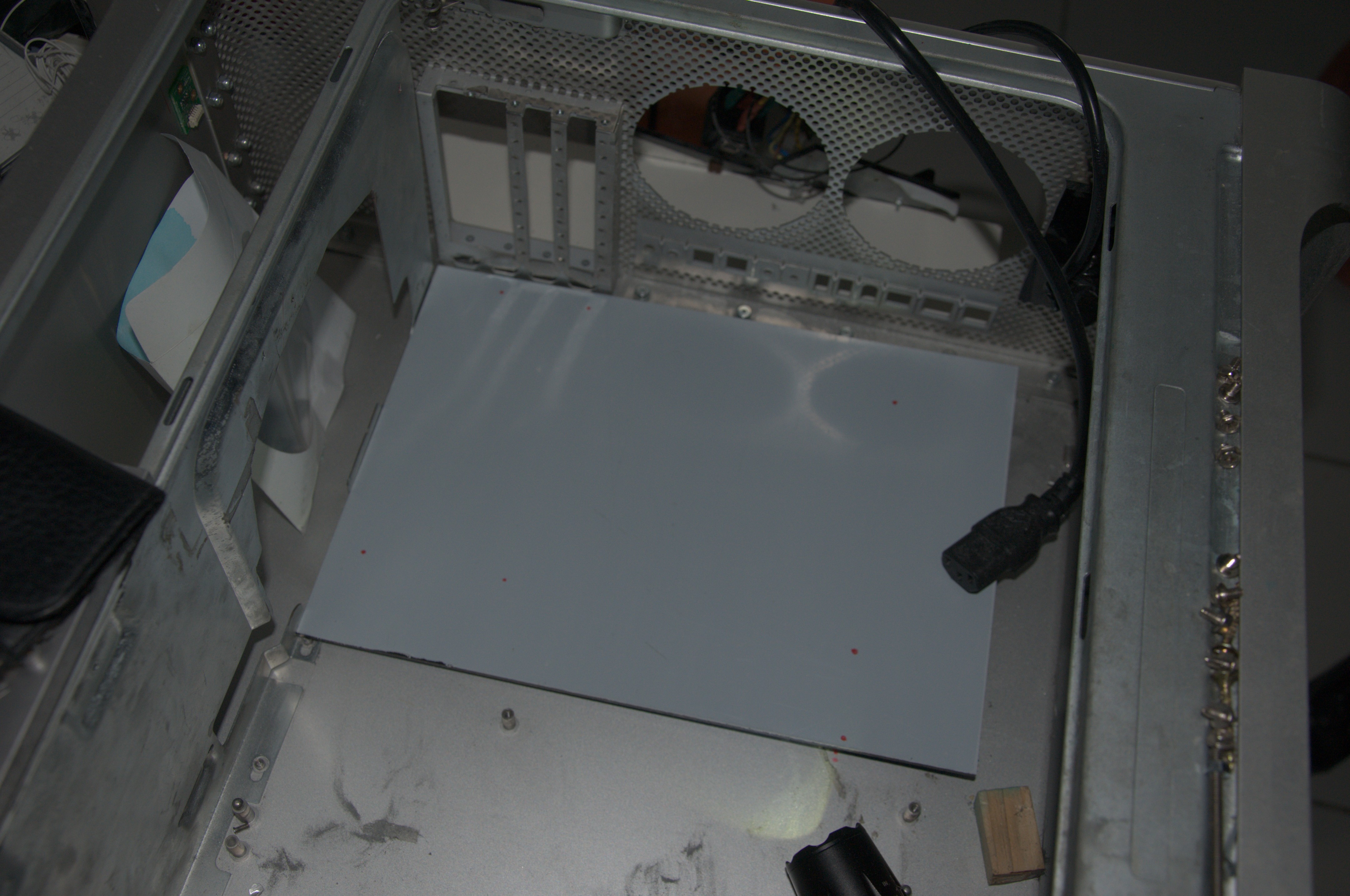
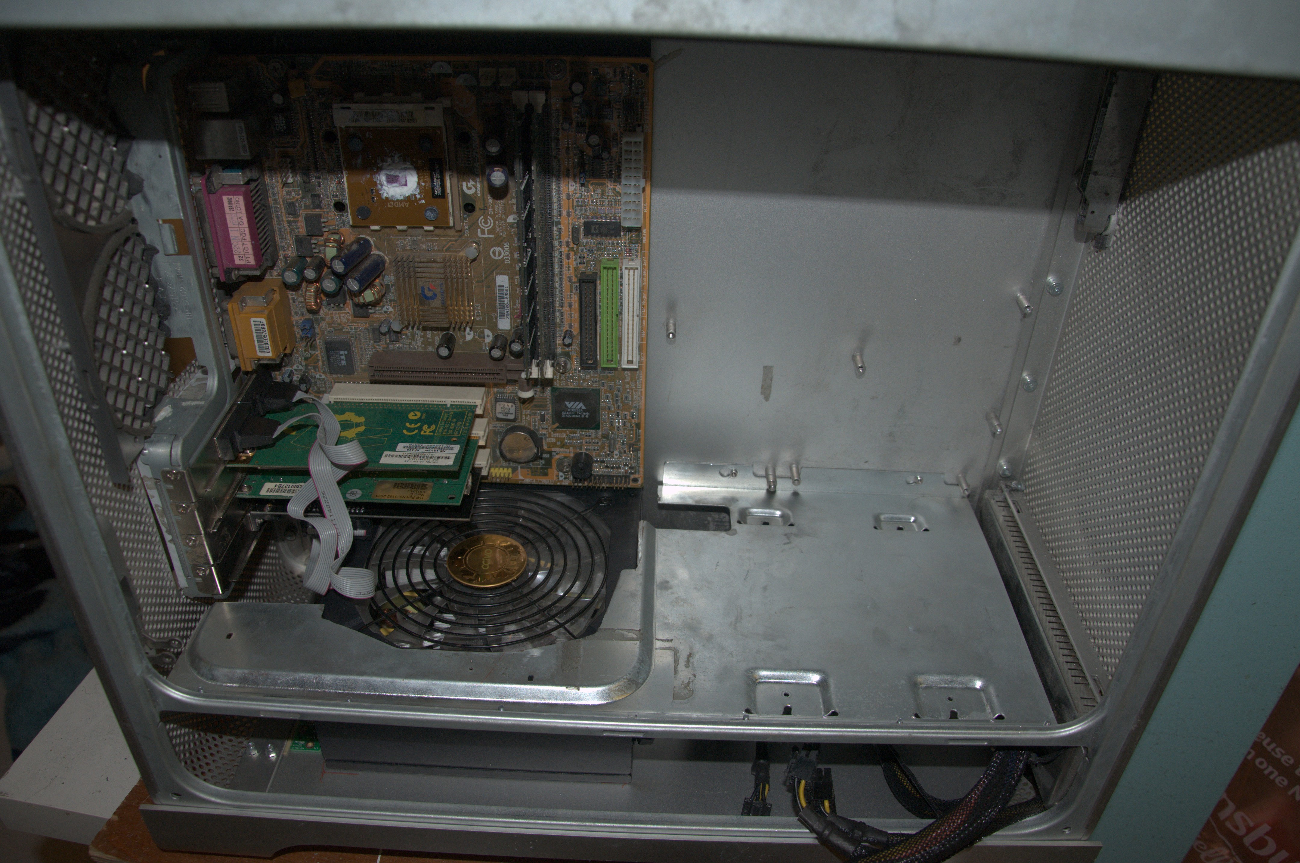
Therefore I decided to make it fully ATX compatible, in this case the micro-ATX standard seemed the best fit. It would allow me to shift the motherboard to the rear of the case (opening up internal space), while also making access to rear connectors on the motherboard and PCI much easier (no need to pull the computer out and take the side cover off just to (de)attach a cable). To do this I first had to empty the G5 case and then I used an old micro ATX motherboard to check fitment. I had to make sure that the PCI slots would align with the case PCI mounts, as shown:
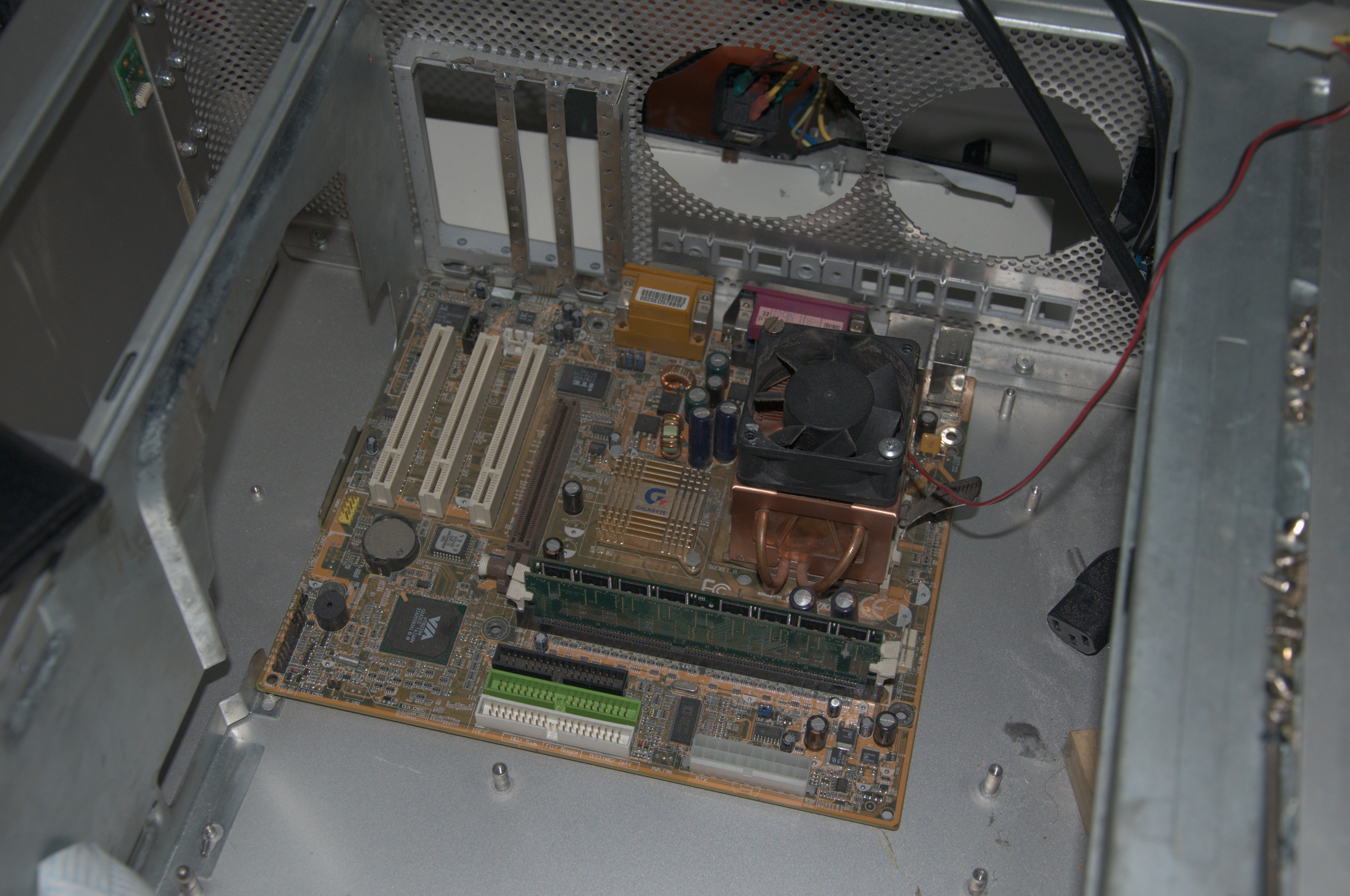
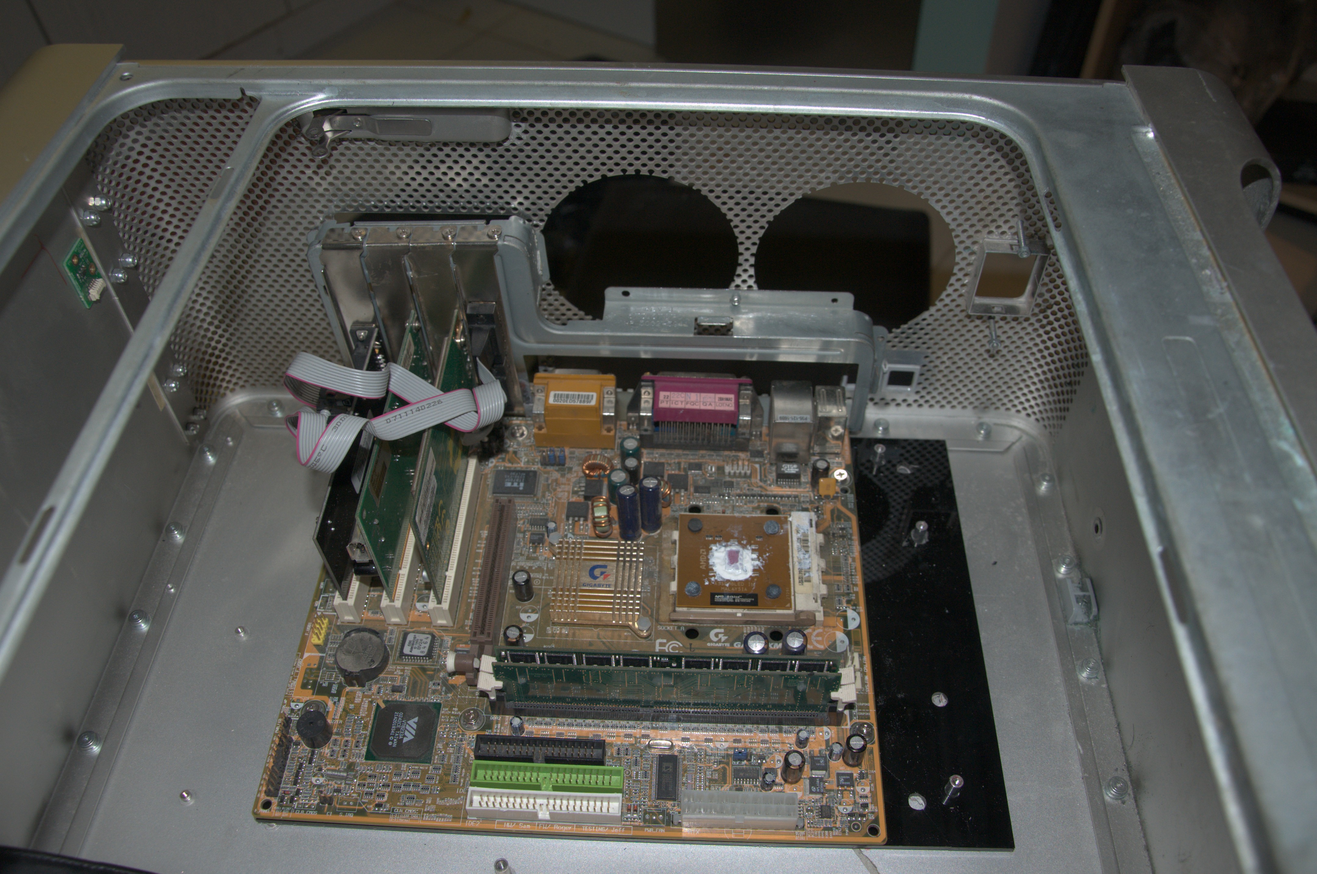
The good news is that the offsets are correct, and you can fit a PCI card just fine. The bad news is to do so, you have to remove the top shelf. It unfortunately fouls the motherboard if we position it so we can make use of the PCI slots. Considering the main goal of these mods is to make the PCI slots and I/O align, I can't move the motherboard lower. So instead I had to cut more chunks out of the top shelf, as shown below in before and after pics:
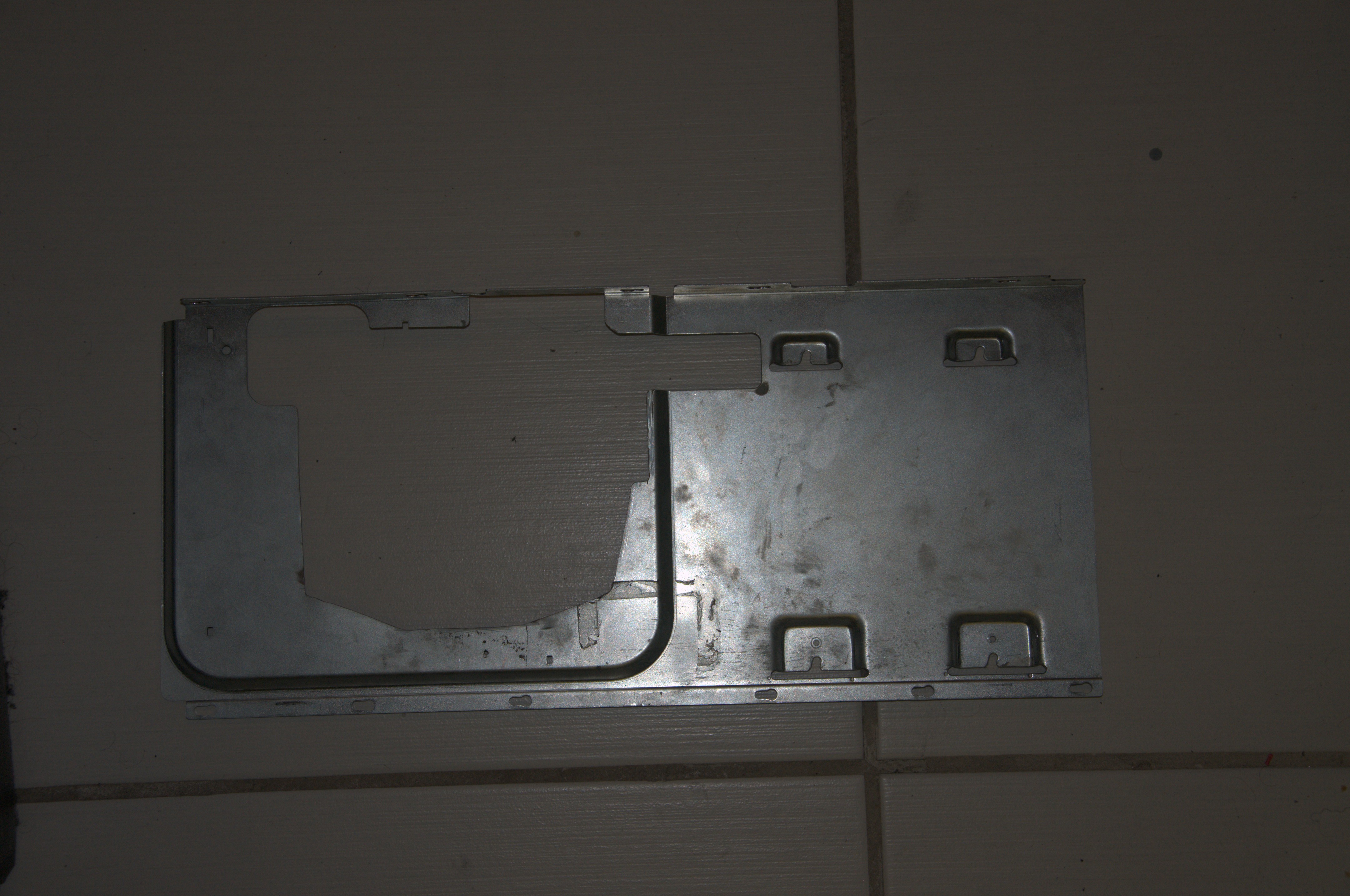
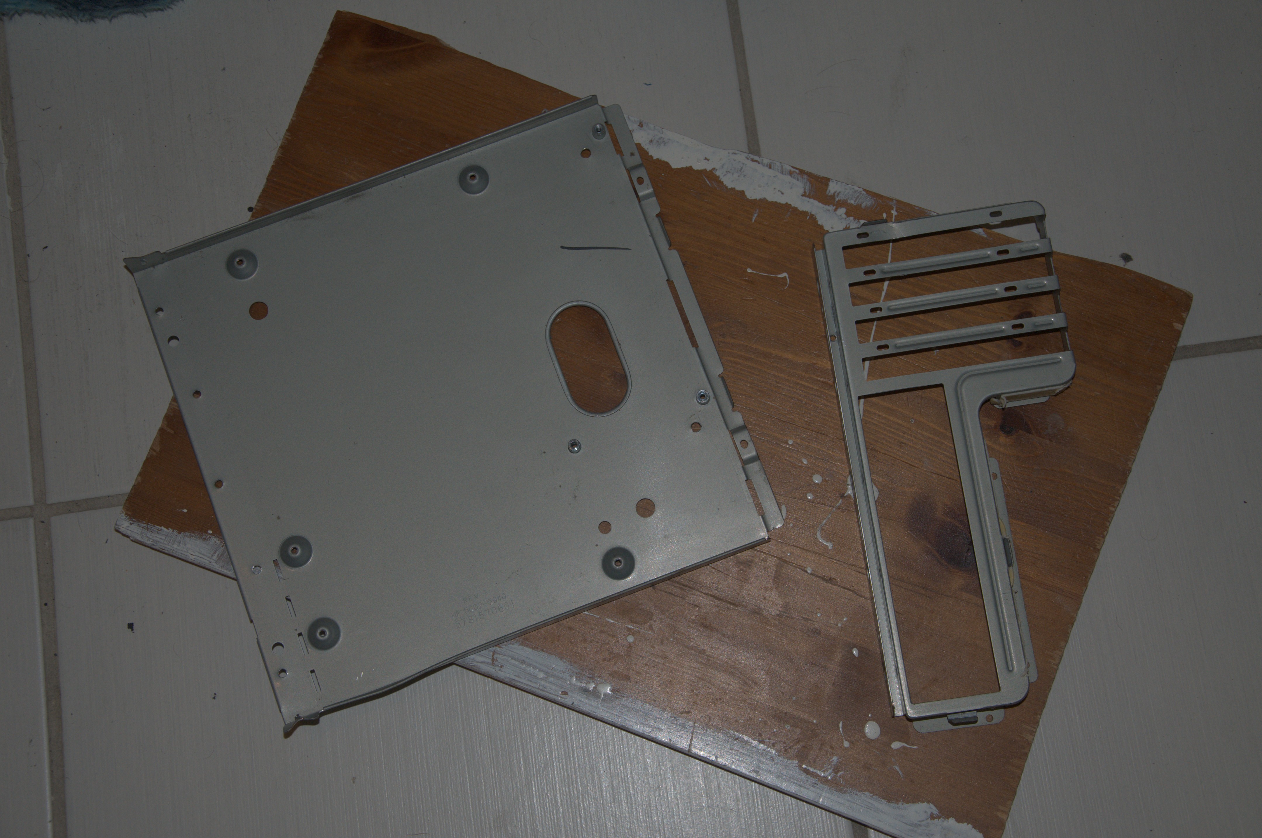
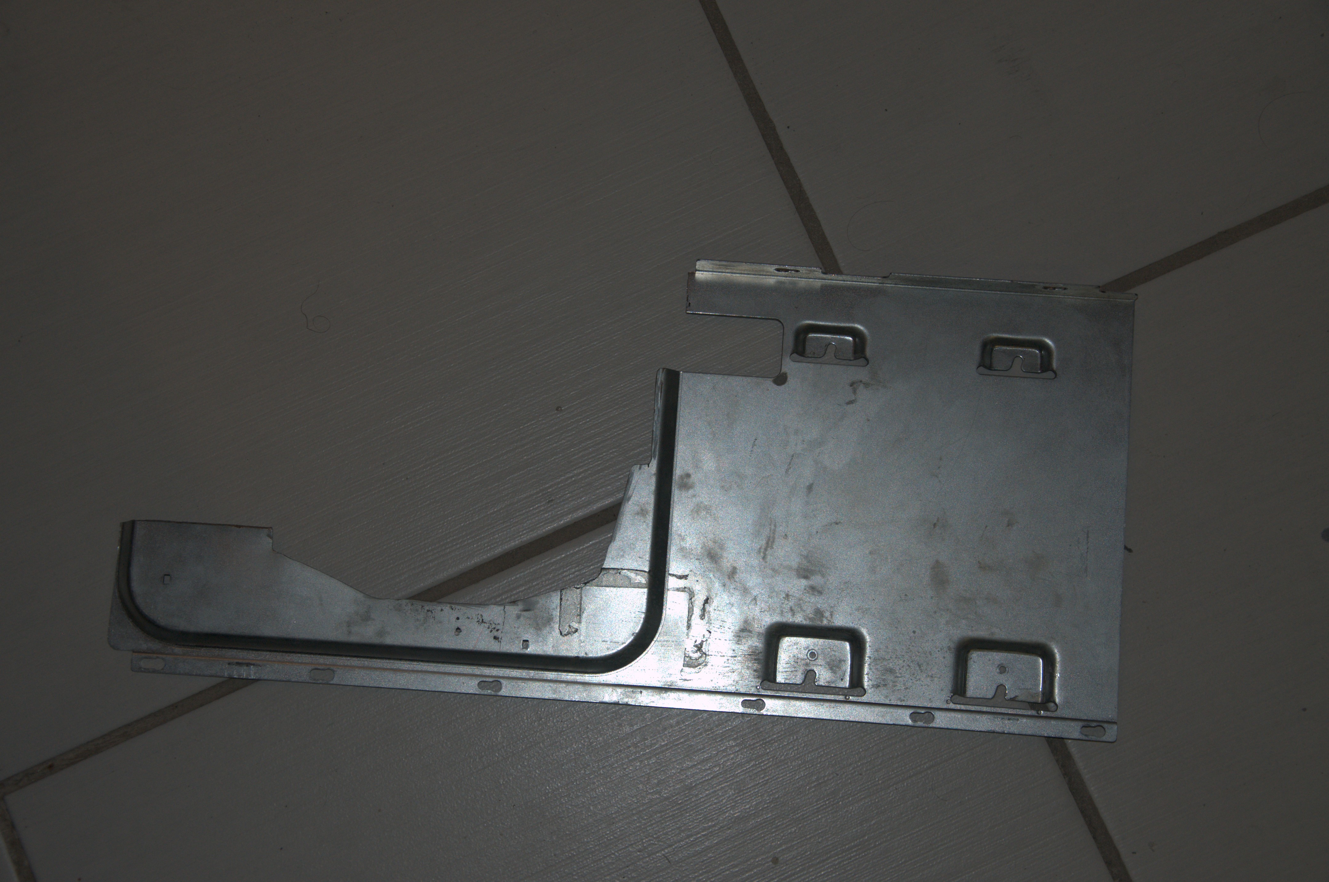 This resolved the fouling issue, although I did start to worry if there was enough material left for the shelf to actually function (as now it only has three load bearing points rather than four as before). The next stage was to take an ATX tray from another PC. I happened to find one in an old Micro ATX PC I took apart (A Compaq Presario 5000 from what I remember, quite a cute case in of itself). It had a nice feature that the ATX mount and PCI panel came out as one unit as you can see:
Unfortunately I found that I could not make use of the ATX tray mount, as it left too much of a gap to reach the PCI slots, so I detached the ATX mount and left the PCI and motherboard I/O panel.
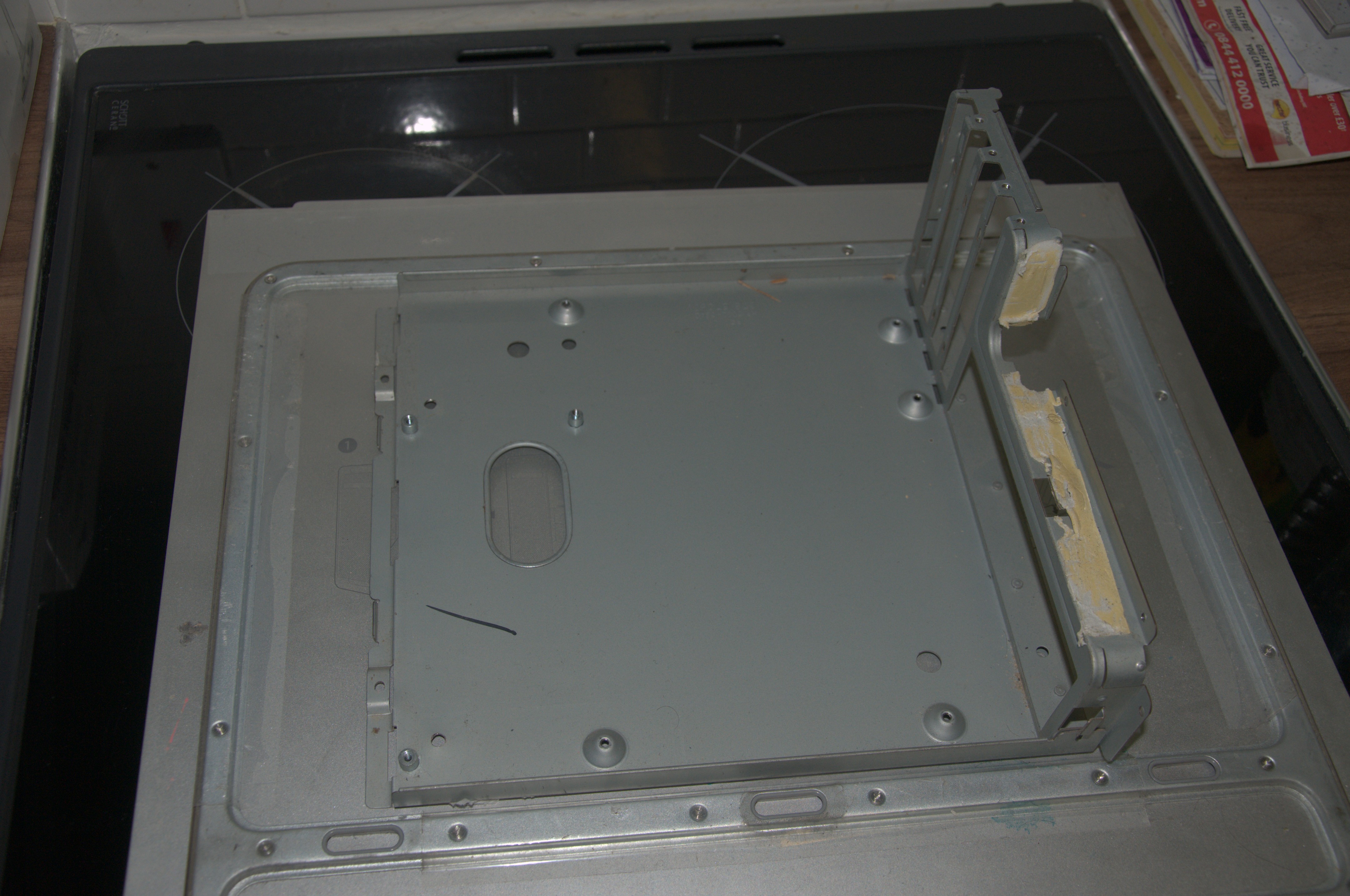
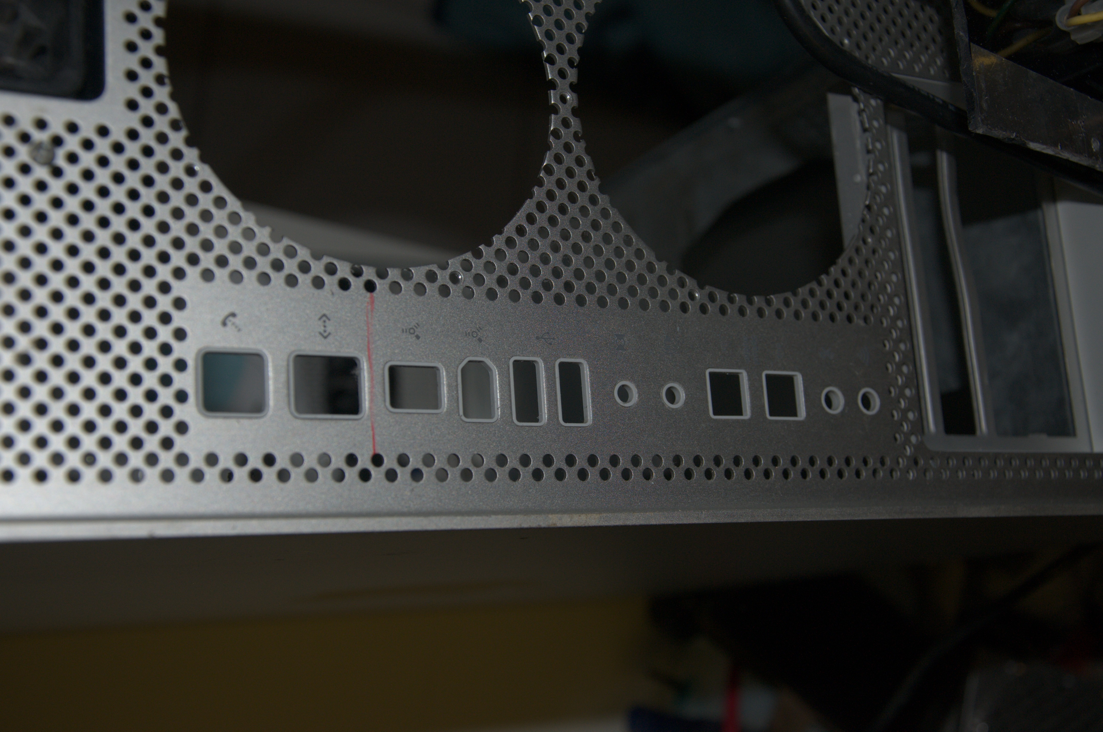
First thing I had to do was cut out a hole in the rear of the case for the Motherboard I/O mount. This is the one part that needs to be cut out, as the rest fits just fine, so I marked out the area where it needs to be cut and then I went at it with the Dremel. The result:
 a
a
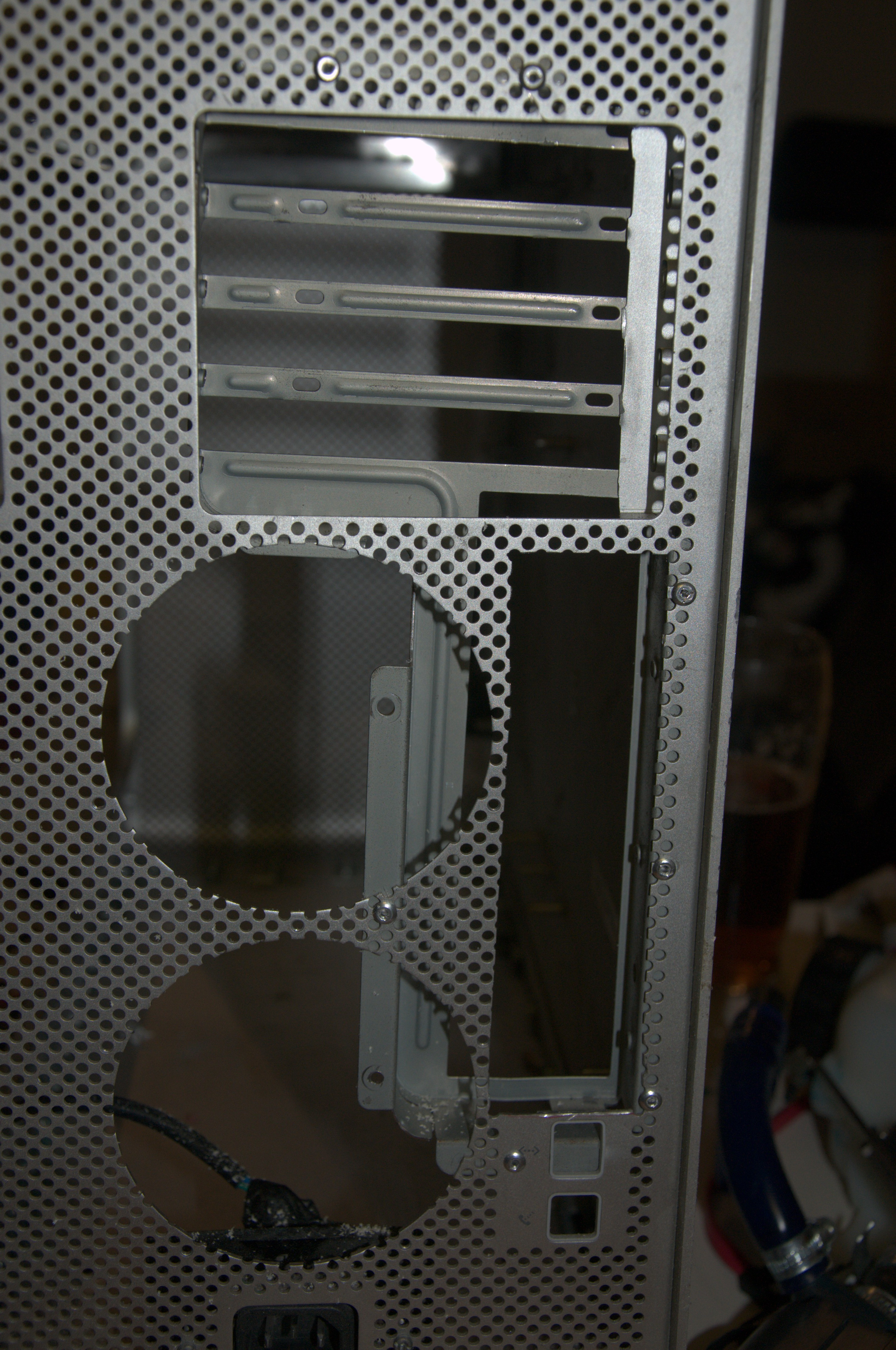
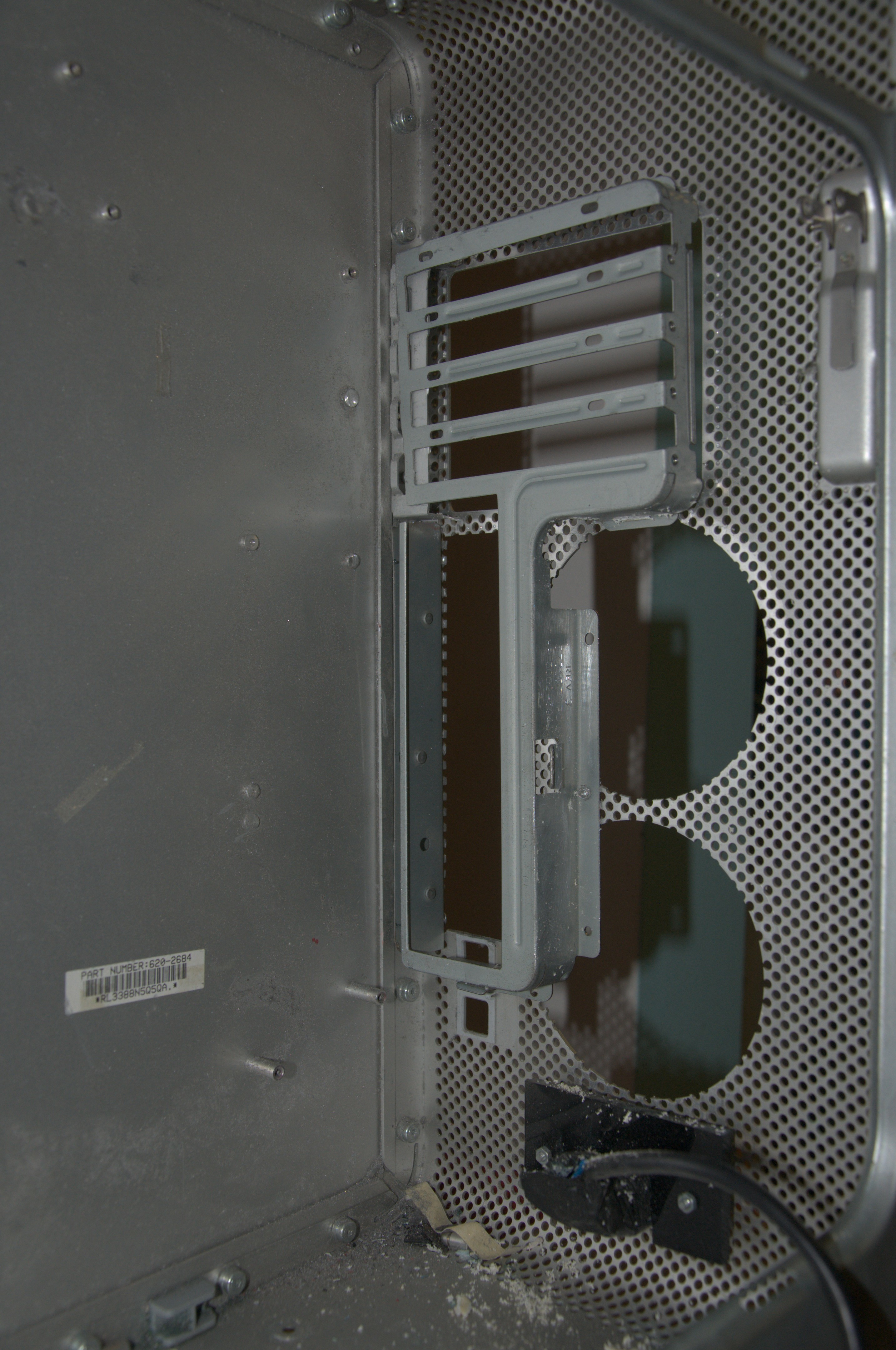
Then I used blind rivets to rivet the I/O panel to the case. Turns out the apple G5 case holes are the right size for blind rivets, so I did not have to drill any holes to do this, which was nice. Below you can see the I/O panel done. Unfortunately we do now block the fan mounts, so we can't fit any fans here. This is fine as the front panel fans are plenty for cooling (the original G5 case had no front fans, only the rear ones), but it does mean we had to cut the fan grills so they could fit in the semi-circles we have now created.
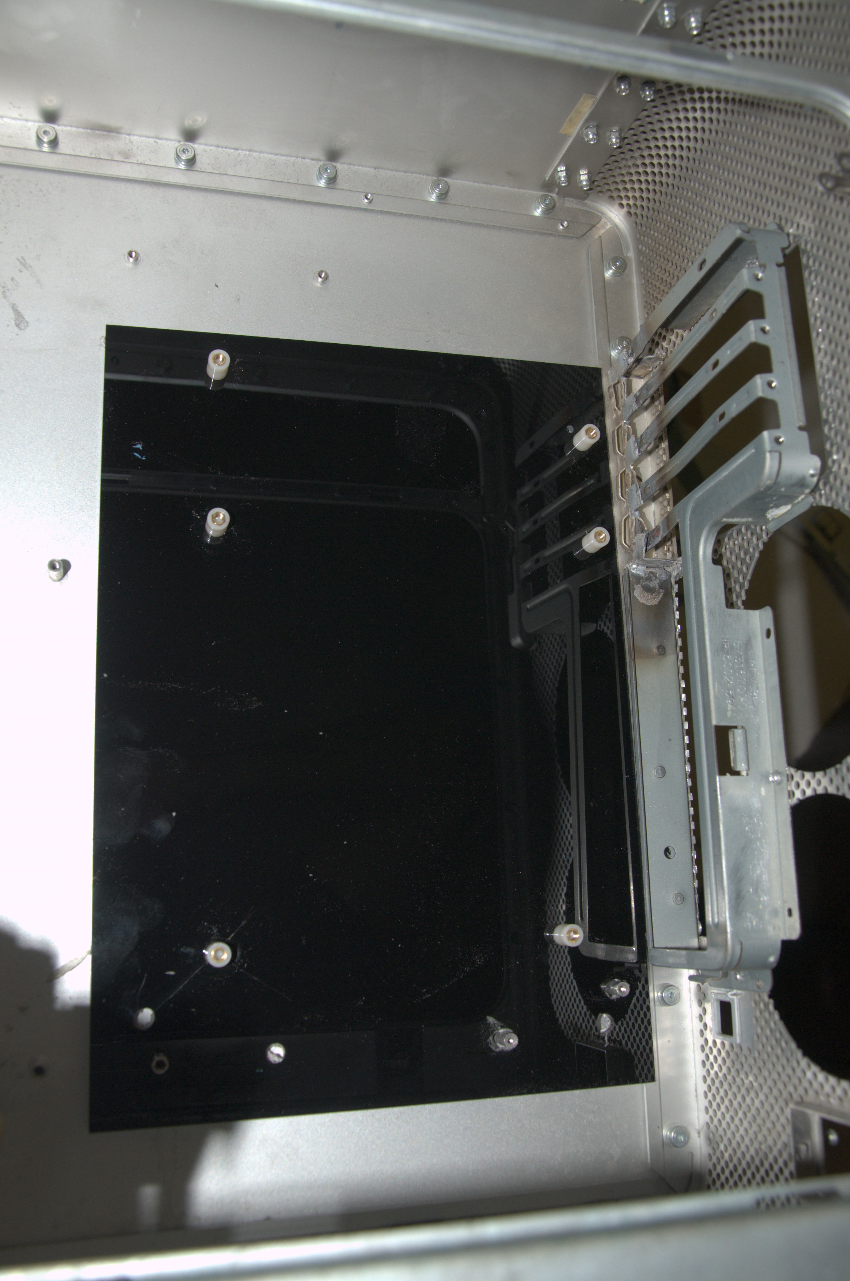
With that bit done, the next step was to fabricate an ATX mount we could use. For this I went to my usual staple of acrylic sheets, in this case a black 3mm sheet I had available. First step was to mark out where the existing Apple motherboard mounts were, then cut holes to use them as registration pins. Once this was done we then marked out and drilled/tapped holes for motherboard standoffs which allows us to mount in the correct position.
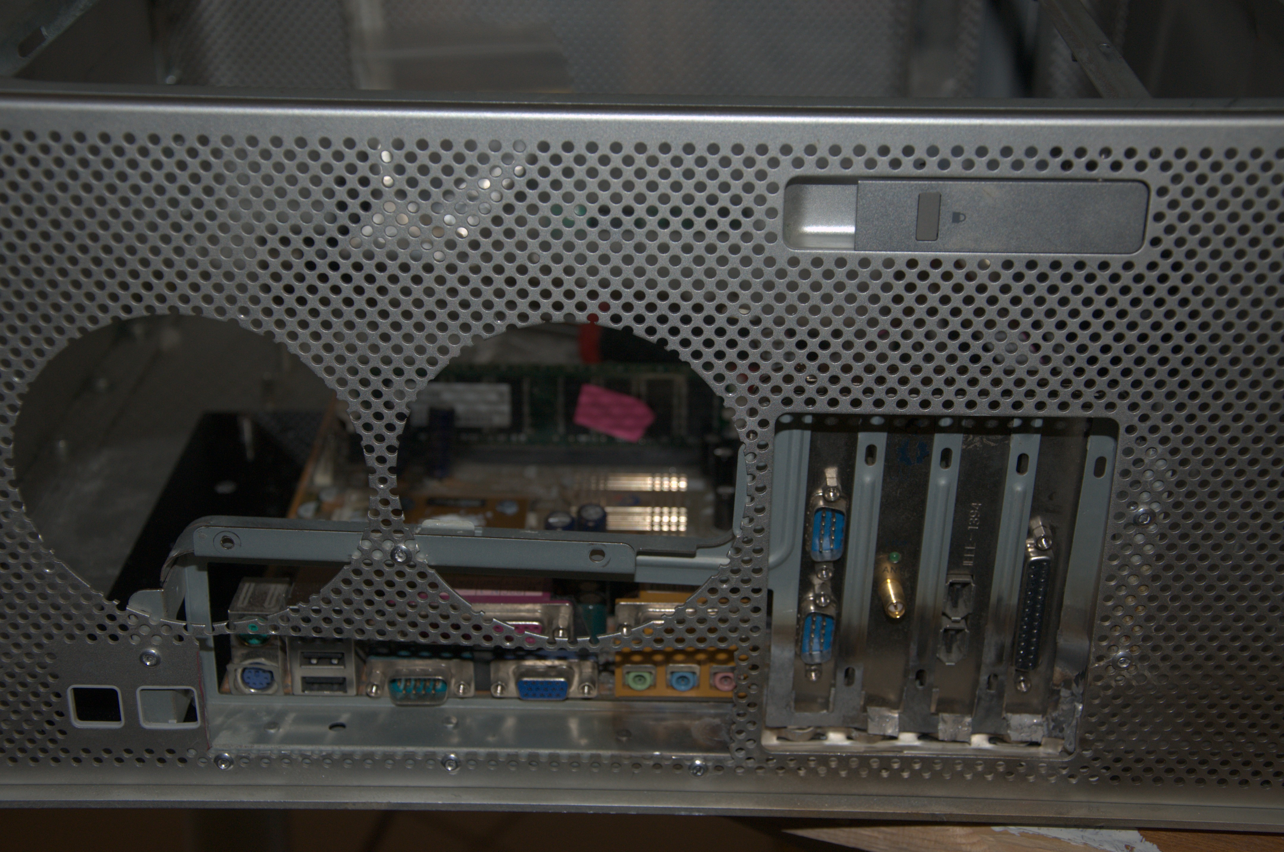
With this done, the motherboard was offered up with a full complement of PCI/AGP cards, to confirm it all aligns correct. Good news is that it did align as designed:
With the location confirmed ok, we applied impact adhesive to the bottom of the black acrylic base, re-mounted all the components to keep the alignment, and then left it for the glue to set over the next 24 hours.
Once it dried, we re-fitted the newly cut top shelf and PSU, and confirmed that everything fits exactly as it should.
As you can see, the extra cut out on the top shelf gives us just enough space to mount the motherboard and prevent fouling. I was worried that there would not be enough metal on the shelf to hold the ATX PSU in its proper position, but thankfully it looks like it can do it just fine. There is no risk of the PSU leaning down onto the motherboard, instead it will stay fixed in the desired location.
New front fans
I also decided that it would be a good idea to upgrade the front panel fans. The previous setup used a very thin clear acrylic which was flimsy, and with time it started breaking. So this time I decided to re-make it using much thicker 5mm acrylic, this time in a pearl white colour instead of the clear acrylic used last time.
Now that we have moved the motherboard to the rear of the case, we have more internal space. As such I am moving the fans further back. The "Mark II" had the fans near flush against the front of the case, blowing onto the radiator. The result of this is that I could get two circles of dust forming on the case in front of the fans. This is due to the fact the fans were so close to the front panel they would suck in air from directly in front of them, creating a localised high vacuum area and concentrating dust accumulation. By moving the fans further back we remove the local high vacuum area and draw air from across the entire front panel with lower airflow per unit area. This should hopefully prevent the dust Circles occurring in future. In addition the extra space created by moving the fans further back will let us fit a dust filter, so that as much dust as possible is captured before it clogs the fans and other internals.
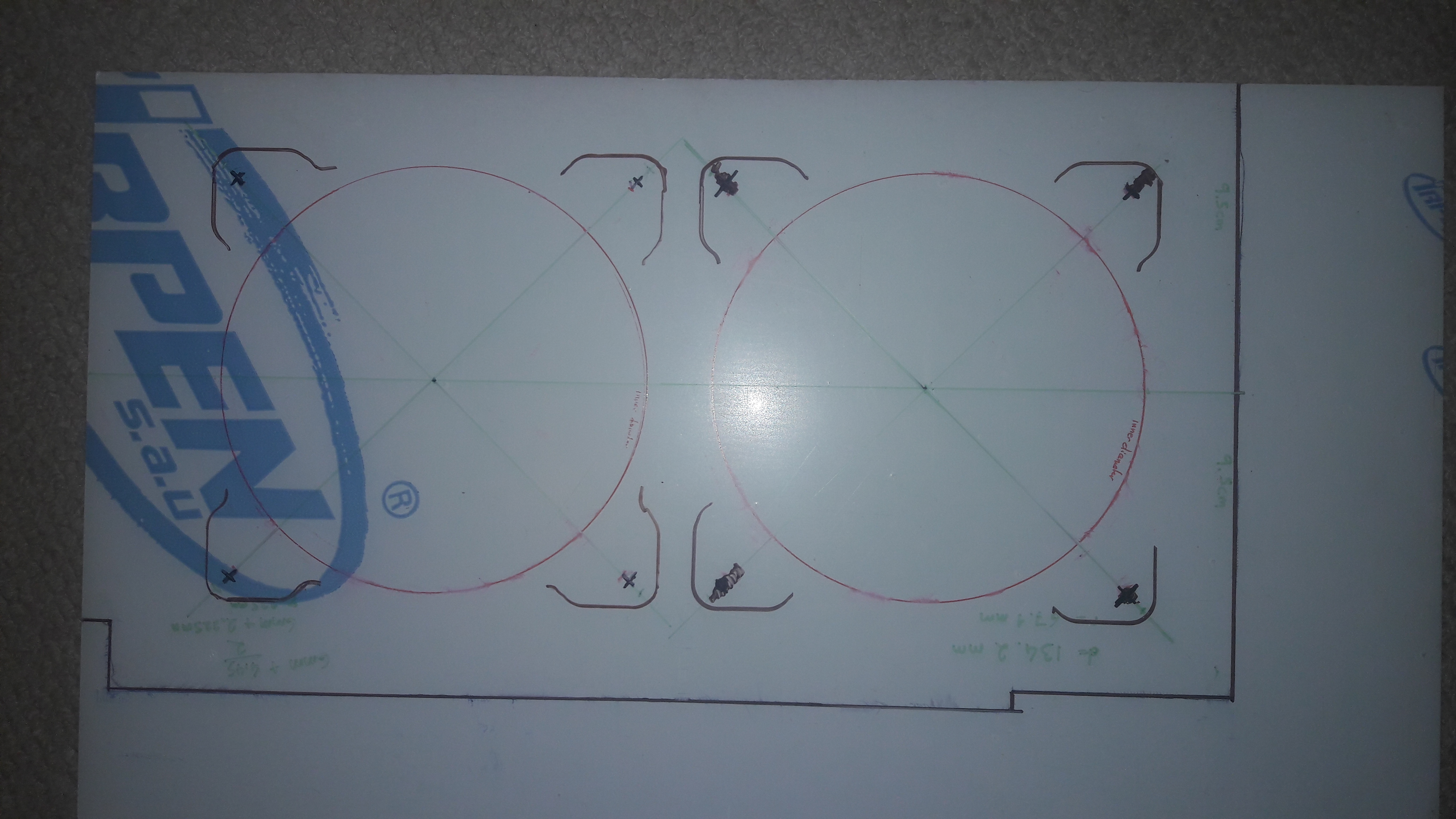
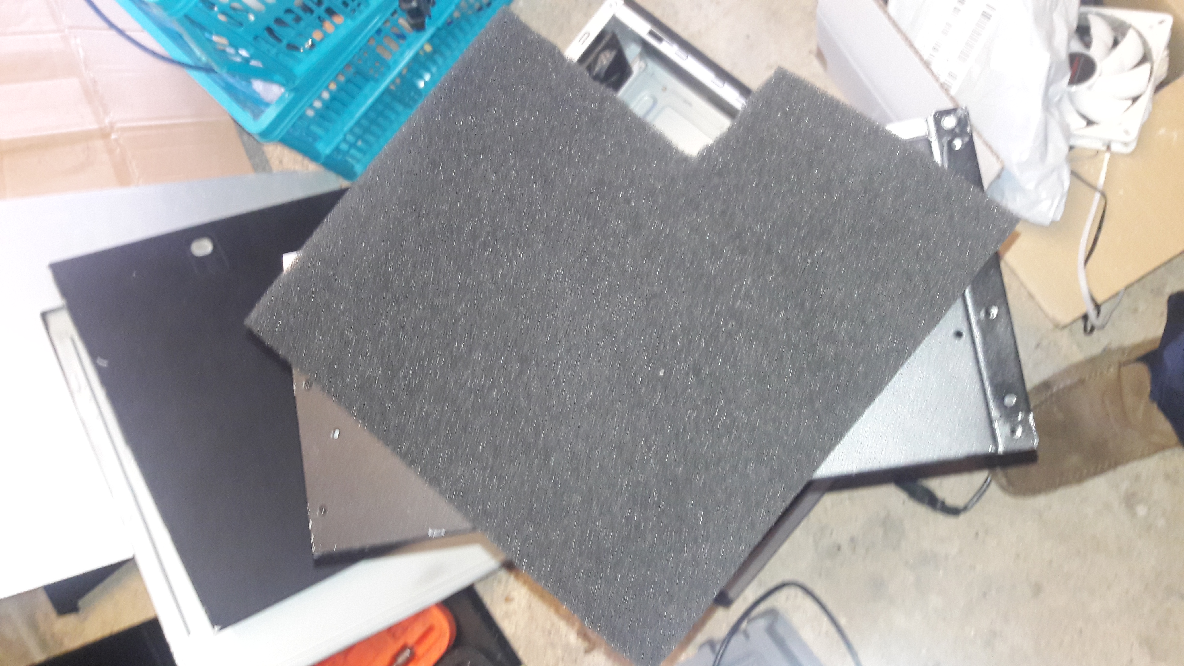
So I started drawing out the patterns for the 120mm fans and their mounts. This was easier said than done because not being clear acrylic I could not place the fans on one side then easily mark on the opposing side where to cut and drill. I had to painstakingly measure, mark out, remeasure, verify and triple check all the markings were correct and aligned (hence why you see all the markings on the acrylic sheet). Surprisingly I could not find any off-the-shelf templates for computer fans online. Despite the fact that it seems to me that the mounting holes and fan diameter seem to be standard across manufacturers, so this took a lot longer than I envisaged.
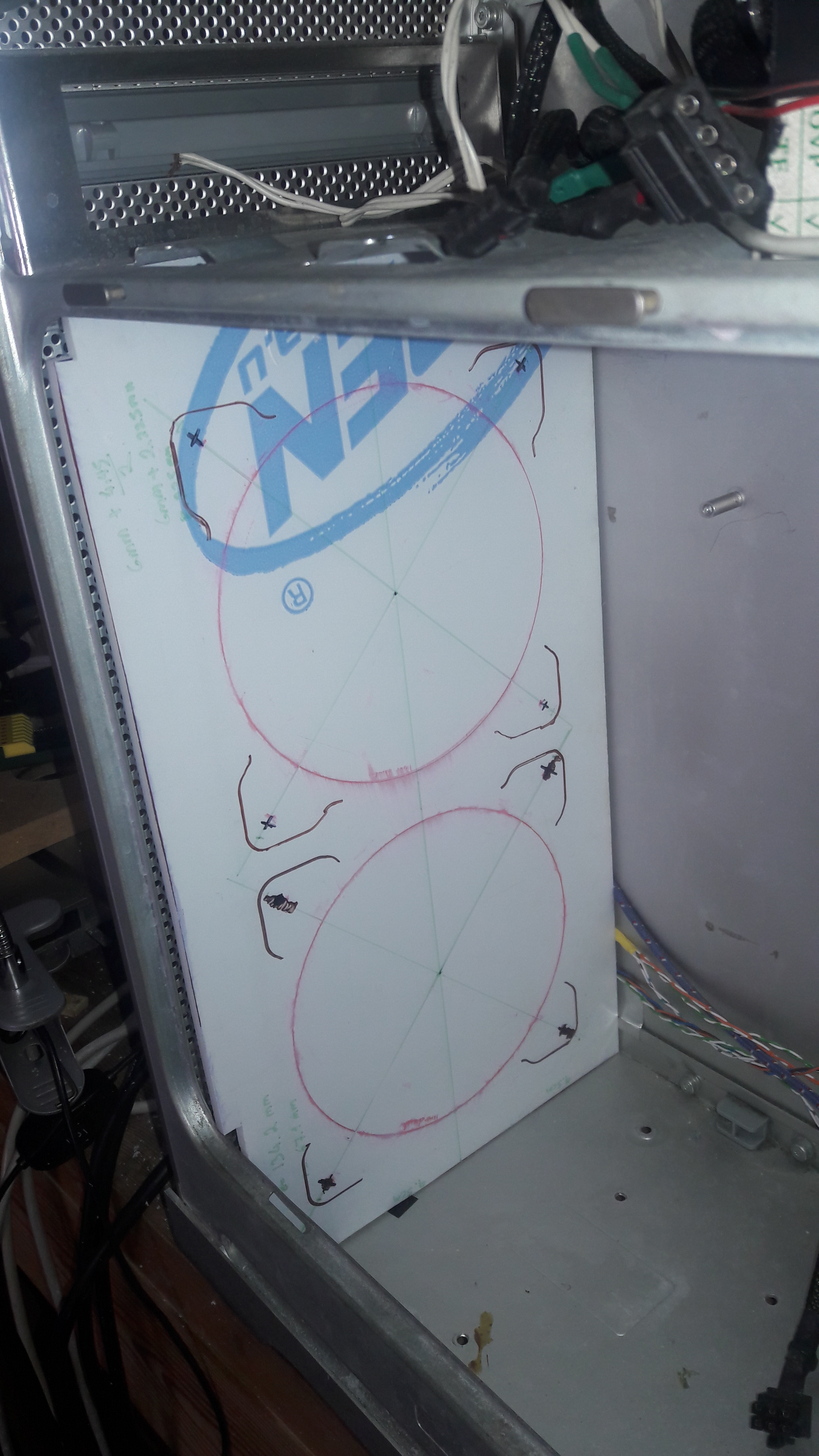
As we have moved the fan panel further back we did not have to cut a notch on this panel for the face connectors like the last one. Instead we can go all the way to the wall, minus a few mm so that the cables can pass through (you can see them on the bottom right of the second picture above). Once we had a good confirmed fitment to the case, I got to work cutting the holes with my new trepanning tool, which gave us good sized circles to fit the fans:
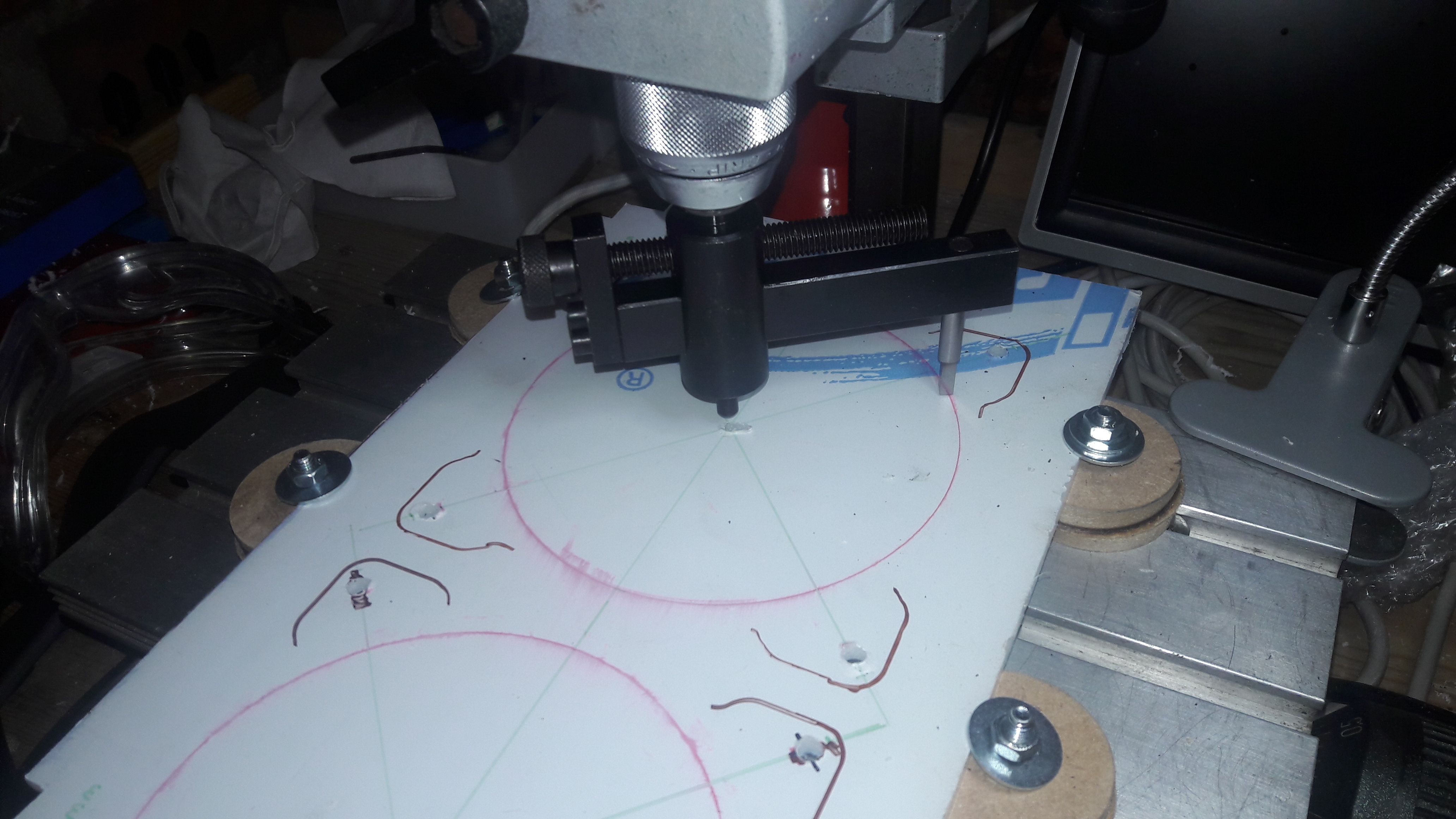
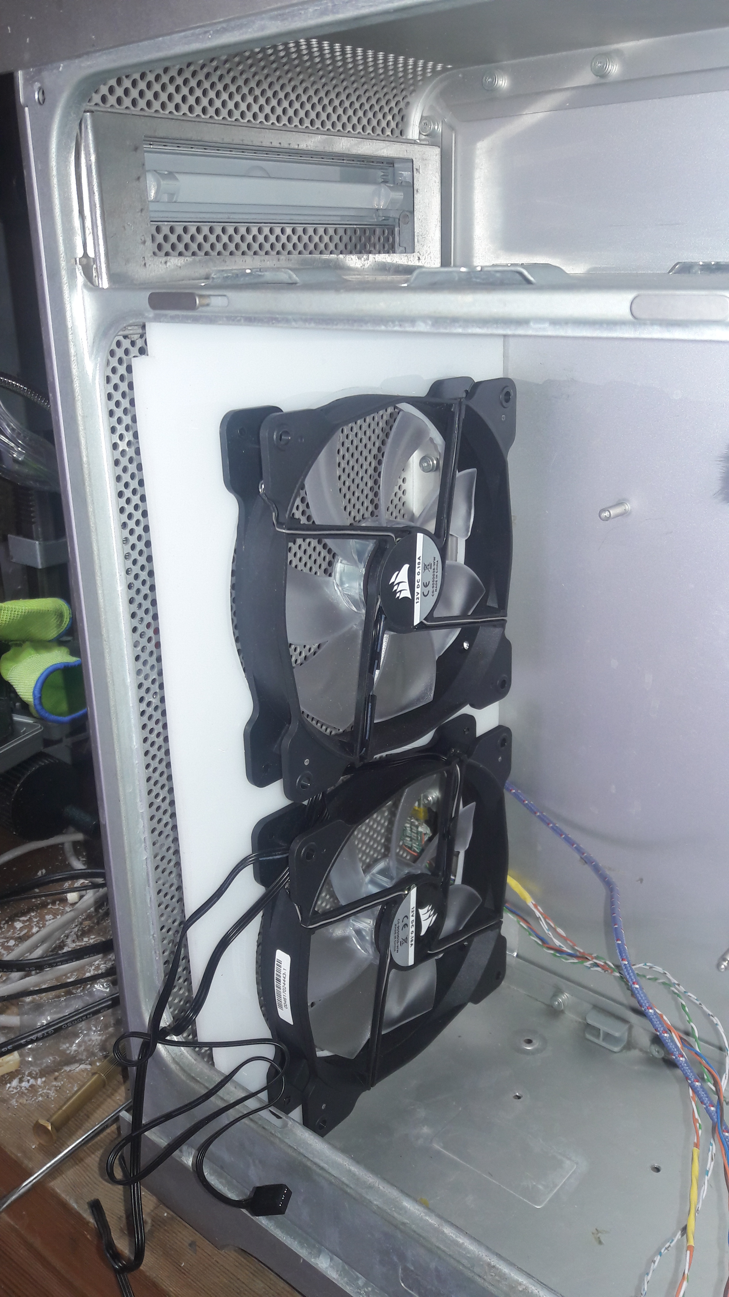
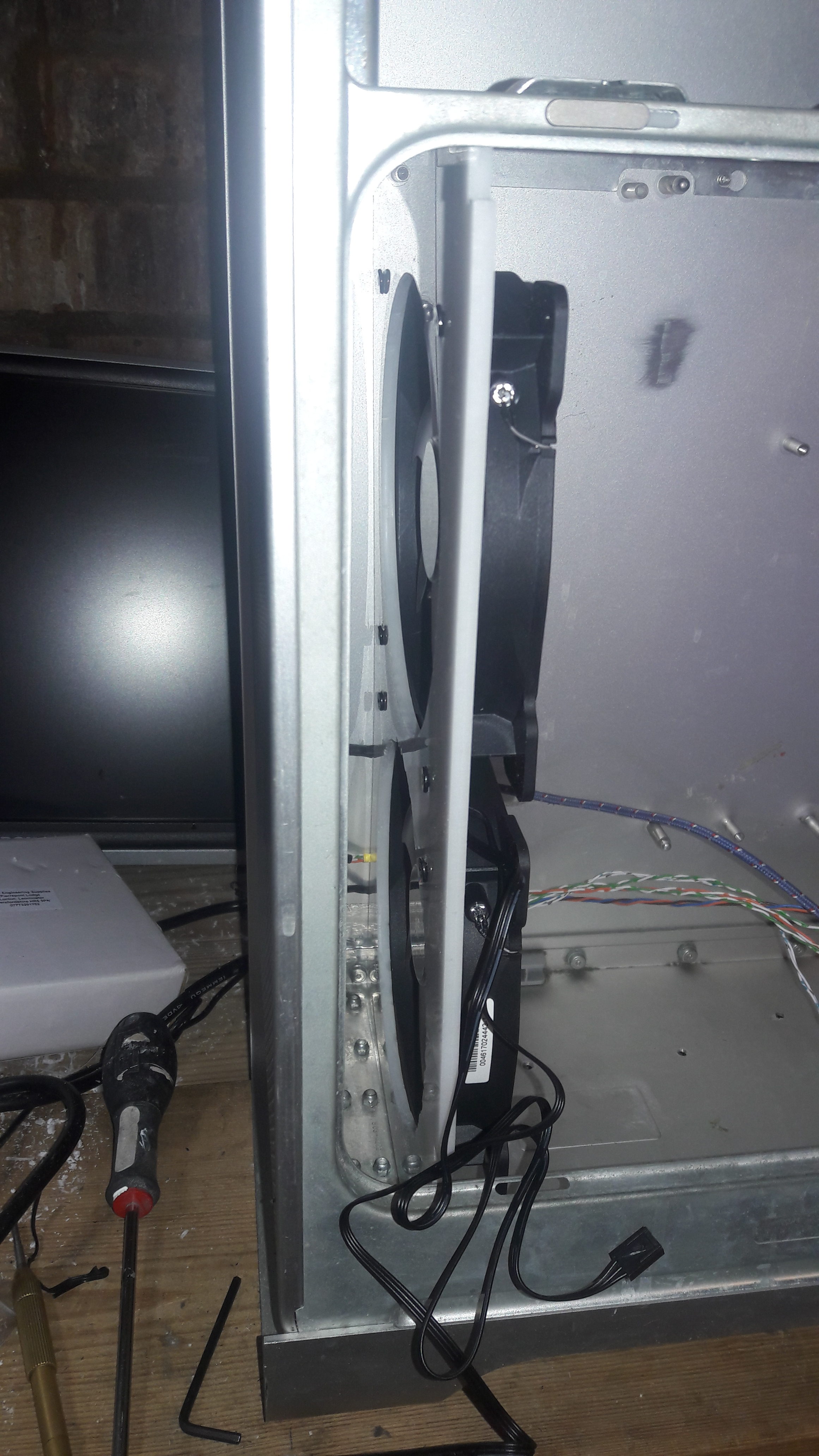
All done and fitted! It is nice when something created and put down on paper comes into physical being. I'm happy with it and it was a lot easier and more accurate to do it with the trepanning tool vs manually filing it down with a rotary tool. We also have space for the filter at the front as was desired. When powered up the fans give of a violet blue glow which I admit looks quite cool, but I feel it doesn't really fit with the elegance of the case, and I would like at least the front to remain looking original.
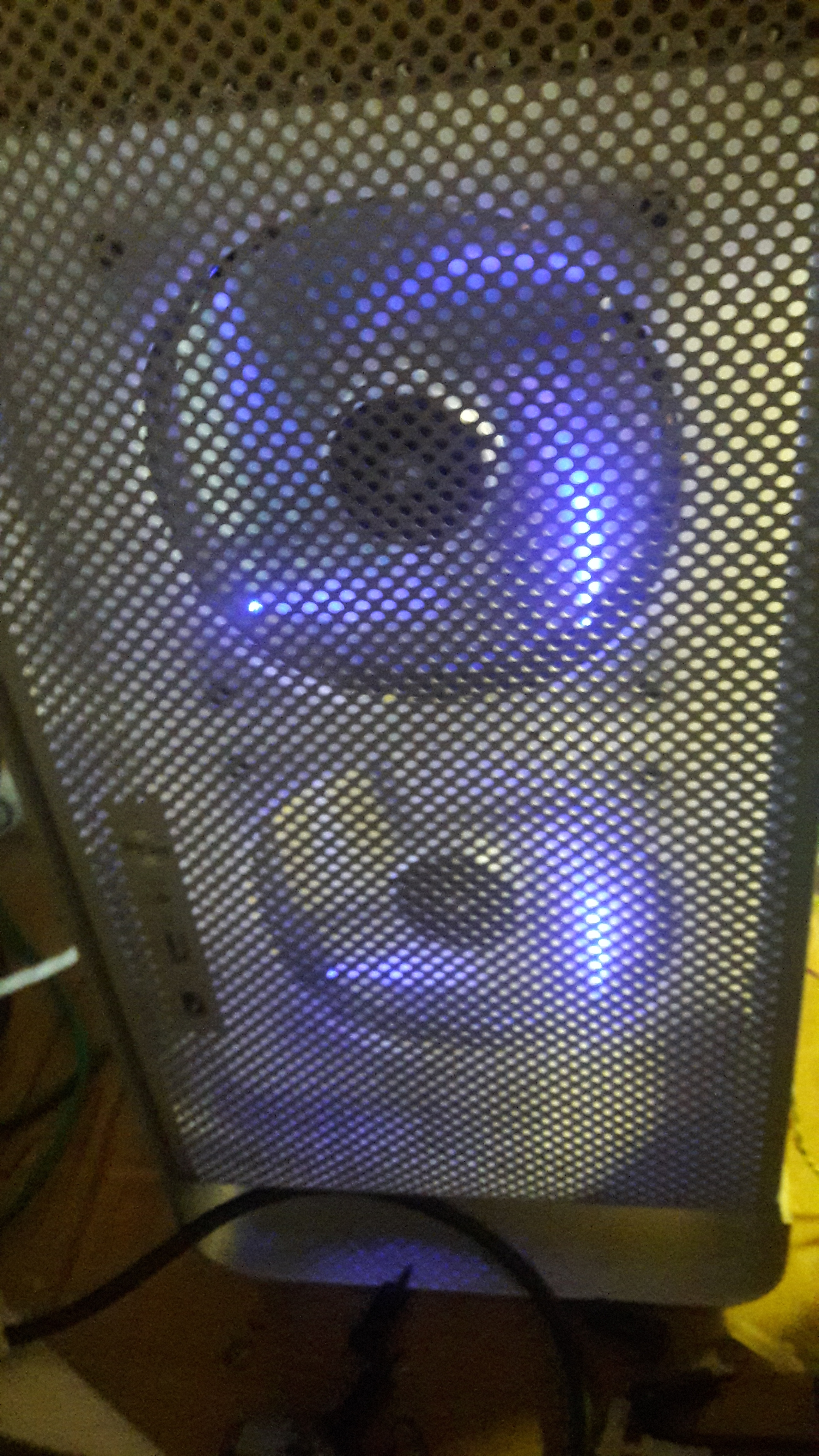
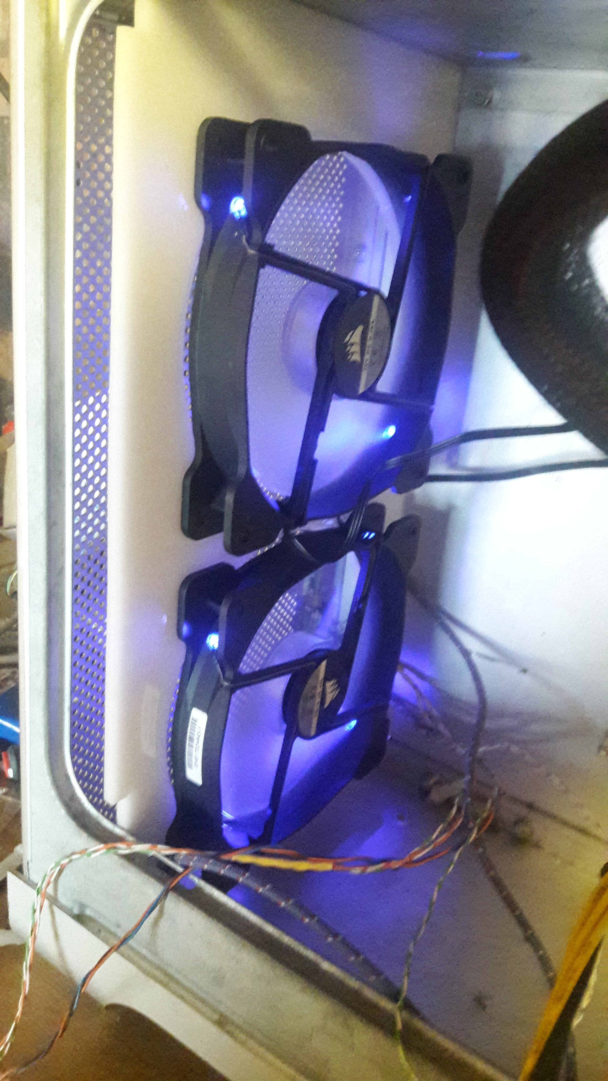
The plan for the moment is to leave the violet fans as they are, on the premise that fitting a dust filter in front will block most of the escaping light. With any luck the violet will only be visible when the machine is in a dark room, but wouldn't otherwise be noticeable. If the violet is visible through the dust filter under normal conditions then I may see about cutting the power to the LEDs.
Speaking of dust filters, I had to find something that would be good for the task. After some research I settled on motorcycle air filters. They tend to be air filter panels, so you can buy panel filters online quite easily and they are easy to cut.
Here is the panel filter, and I've already started cutting it down to size. The plan is to have one flat panel against the front of the case, then side filters to fill any gaps between the fan panel and the case. This way very little air will be able to bypass the filters and go into the inside of the case.
Motherboard fitment
When it came to the fitment of the actual motherboard we would use rather than our test board that we used for mocking up, we came across a problem. The new motherboard fit fine in the mount, but the motherboard PCB lip extended a few mm more than the mock MB. The result of this is that it would foul the PSU, preventing us from mounting it properly.
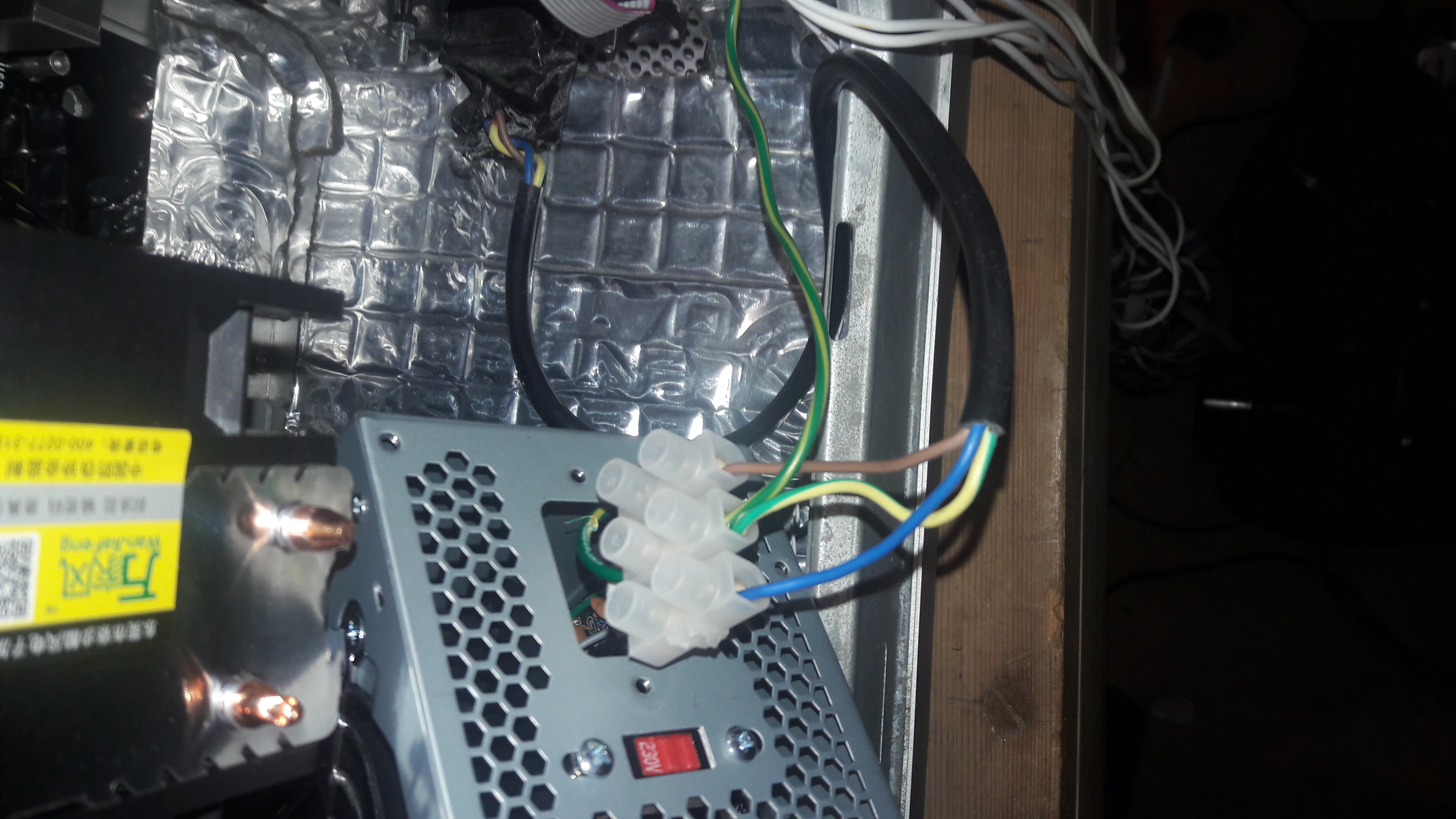
This means that despite the cutting of the upper shelf to make space for the PSU and MB, we can't use that layout. Instead we will move the PSU to the bottom of the case, freeing up space for the motherboard above. After all, we are no longer liquid cooled, so we don't have to worry about putting high voltage systems at the bottom of the case (short of conductive pieces falling into the PSU while running, but I consider that very unlikely). To fit the PSU while still allowing the OEM power socket location to be used, we had to remove the PSU socket and used a block connector to wire it in directly to the case socket, as shown:
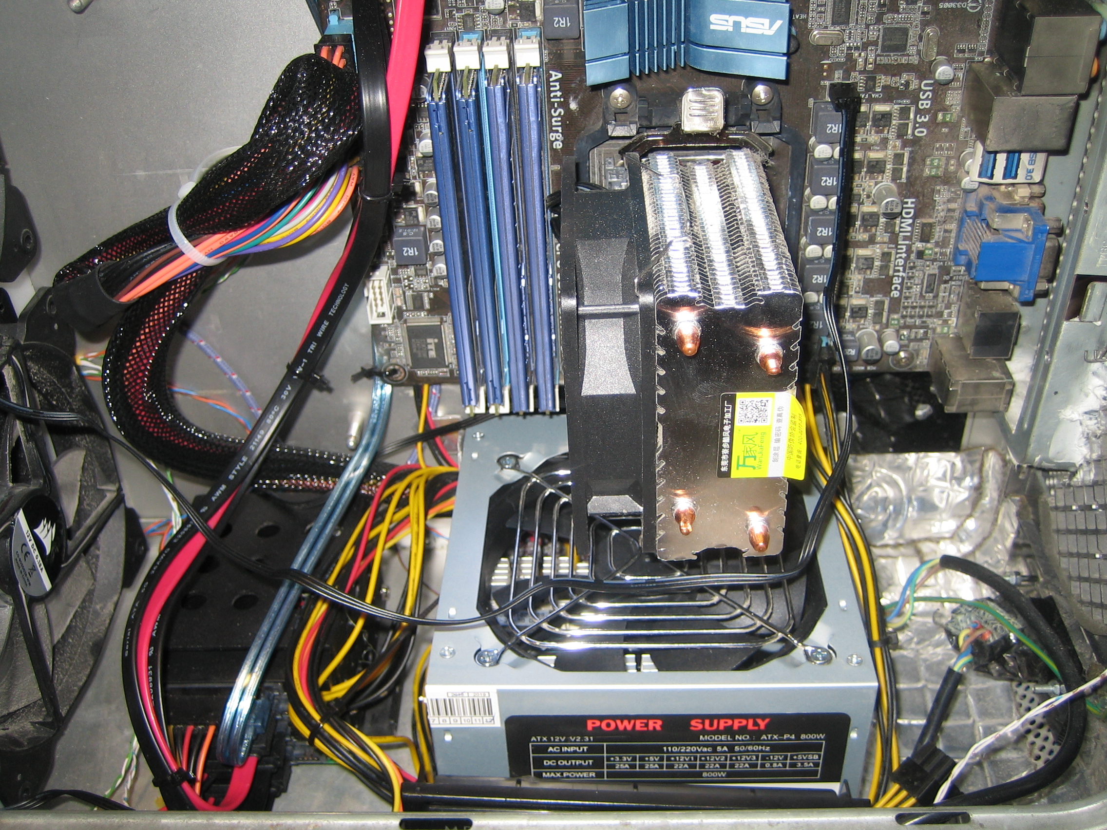
With this done we could fit the motherboard. In this case an ASUS M5A78L-M/USB3 with an AMD FX-6300 processor. Due to the size of the case and a desire to keep it as quiet as possible, i searched for the largest heatsink I could find. Bought this generic finned tower off e-bay and it seems to do the job fine. I was worried if would be heavy and cause sagging when fitted vertically, but it was lighter than I expected and there seems to be no such issue when mounted. Below you can see the motherboard with the PSU underneath:
Sound
The Compaq that donated its motherboard tray for this project also donated to us its speaker. A very decent quality oval speaker (these old Compaqs were very well built I have to say, high quality materials) that I wanted to use instead of having the extra cable mess of external speakers. We found that you can thread 3mm bolts through the holes of the case, which aligned perfectly the speaker mount holes. As such we were able to affix the speaker to the rear of the case without needing to do any modifications to either.
A second question was how to drive the speaker, things have changed a lot since when I started case modding. Back then I would have constructed a Velleman kit with the TDA2003 amp IC, given me about 7W of mono power. However nowadays you can pretty much buy anything from China, including individual ready-built modules for things like amplifiers for much cheaper than kits in Europe (ignoring even your labour to assemble, test and debug your work). As such it makes little sense to roll your own from a kit anymore (unless you use it for a custom build, or are building it for the pleasure of building). We don't need any custom work here and the amplifier is tangential to this project, so I ended up just buying a TDA2050 based mono amplifier module, ready to go with 35W of power.
Next issue to deal with is the audio input. We have a stereo output from the motherboard, but only one amp and speaker. The easiest solution is to just wire one of the channels to the input and be done with it, but this loses half the audio information. So I decided I wanted to sum the audio inputs so as to preserve as much audio information in the stereo to mono conversion.
Looking online a lot of solutions to this either involved summing op-amp circuits, which seemed overcomplicated for the task at hand, or "brute force" circuits that basically wired the two channels together, sometimes with resistors to attenuate the gain.
None of these took my fancy. Remembering what I learned before about transformers, specifically their use in audio for isolation and impedance matching, I figured why couldn't I use two of these transformers to sum the signal from the two channels without having to shed energy via resistors. It seemed that a circuit to accomplish this is about as simple as the "resistor" method to build, but would provide better audio output and not unduly stress the amplifier.
The premise is simple, you wire two audio isolation transformers in parallel on one side, and on series on the other. The output would then be a sum of the two inputs, with the transformers handling impedance matching and isolation.
The schematic looks like this:
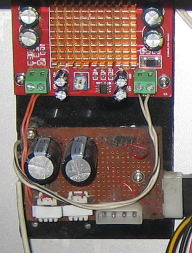
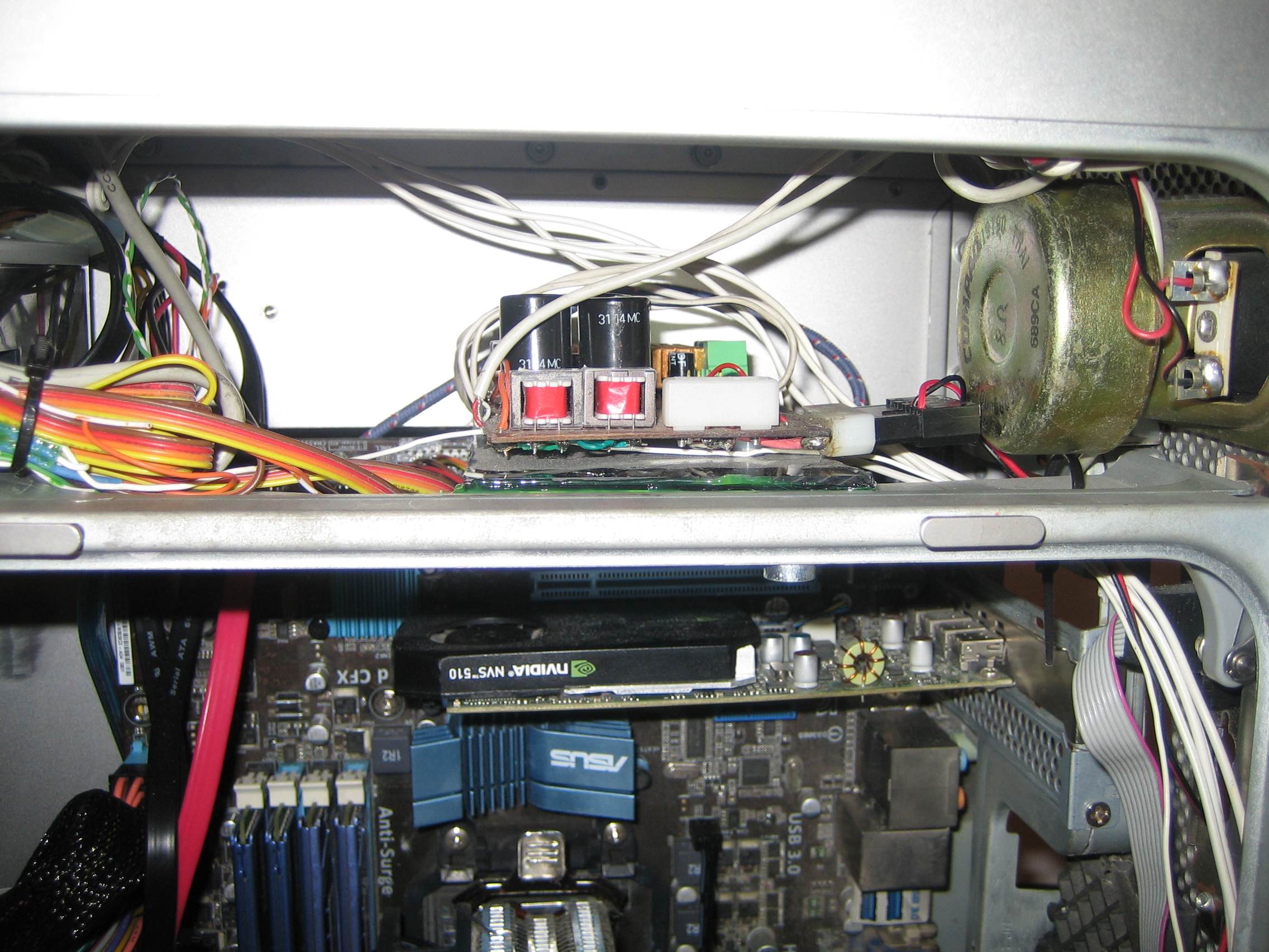
and zoomed in to the amp itself. You can see the two isolation transformers configured for stereo to mono conversion. The capacitors are just to smooth the input voltage and provide some stored energy if needed. Power is fed from a Molex connector.
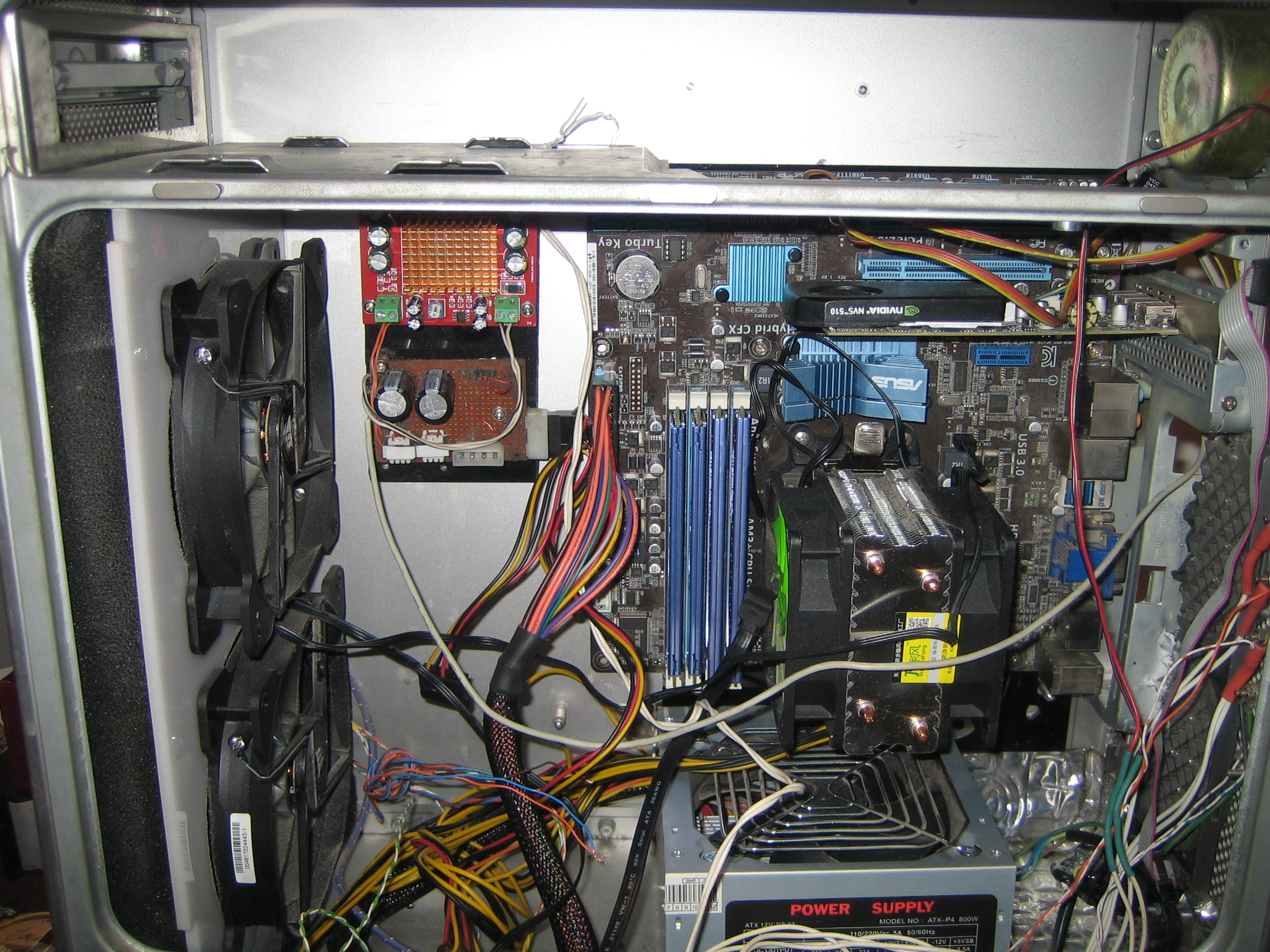
And with that the case is done! A much shorter write up than the "Mark II", but then this project was very much about simplifying things. Everything has been connected up. We mounted the amp next to the motherboard, the drive was fitted next to the PSU and it was powered up successfully. The photo below shows our current state. We have achieved all the objectives, as now we have air filters, quiet cooling and space on the top to fit a DVD drive. Likewise you can see the side filter panel between the fans and the front of the case, which will hopefully keep us dust free.
All that is left now is to use the system and see if any issues crop up :-)
Update: 2022
Well, it has been about two years, which I guess is testimony to the system. There were no major flaws that reared their head. The sound output from the little speaker is very impressive. It is not Hi-Fi quality, but good enough to fill the room and I have felt no need to use external speakers instead. The air filters do a great job keeping the dust out. To clean them just involves moving the fan panel to the side and removing the filters. After which a quick vacuum of the filters and the frontal area, and the system is ready for use again. To date the filters never got so clogged that high temperatures were an issue and the innards have remained dust free, while the system has remained quiet to this day. Also I can say that the violet from the fans is not visible through the air filter unless the room is dark and your eyes have adjusted, so I left them as is.
So for this update it is mostly more refinement and improvement. First thing is to deal with a minor design flaw. The position of the amplifier means that it is tricky to move the fan panel back to access the filters for cleaning. As such I decided to keep that area clean for easy access. I did this by moving the amplifier from its current location to be above the motherboard, where the speaker is (and where I originally expected the PSU to be). Unfortunately this is the place where I cut out the steel panel for PSU fitment, so I had to mount to the amplifier on an acrylic sheet, which was then mounted to the steel panel. Here it is post move (you can see the speaker coil to the right of it, quite a hefty thing):
The result of moving the amplifier meant I had a lot of excess wiring that was no longer necessary. Instead of cutting and re-soldering, I decided to make use of cable ties to bundle them up and as I had the cable ties out, I decided to tidy up the rest of the case innards as well. In addition to being tidy, it will probably help with airflow and cooling in some minor way. I also needed more storage, so I installed a 2.5 inch drive cage at the bottom of the case, far enough away that it does not interfere with the fan panel. This involved drilling two holes on the bottom of the case, after which I drilled and tapped the cage to its location (while allowing for disassembly to make it easier to replace drives). Once done I populated it with 3x1TB drives in raid0 for scratch space, and a SSD for the OS.
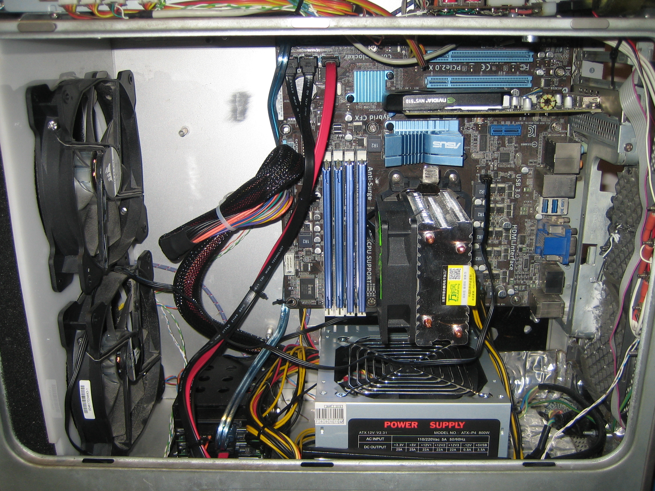
Above you can see the insides now properly tidied up, with the drive cage to the left of the PSU.
We also fitted a DVD drive, which was one of the original goals. It now works like the original, with software tray ejection. The next thing we did was fit a little control panel inside the case. This has power and reset switches, as well as HDD activity lights on it. This was done because it gave me an easy way to control/debug the machine with the case open as the front panel only has the power button. In addition the PCB mount holes were the same distance as the DVD drive mount holes, so I was able to mount the panel on the side of the DVD drive as shown below (with motherboard standoffs so there is no short circuit) as so:
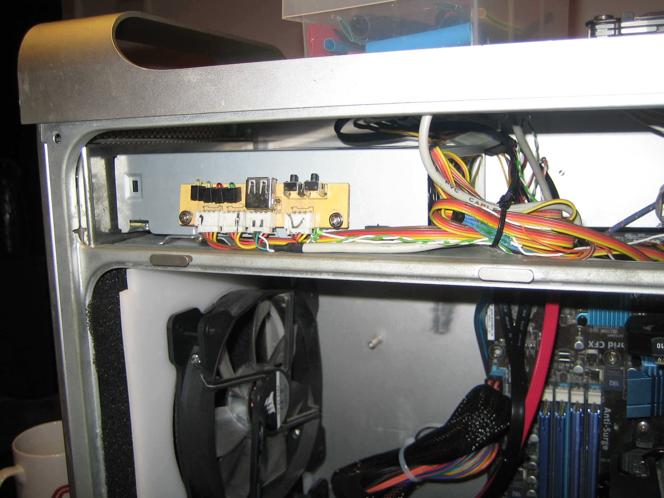
I found another advantage to this layout. With the case closed, you can actually see the activity and power lights, but only at a specific angle. At 95% of the angles the case looks stock, but if you look in one particular way, you can see the panel lights. This allows me to check on the machine activity without needing to add excess panel lights to the front of the case.
Speaking of panel lights, I decided to wire the original white LED at the front to the power LED of the panel. Up till now it was just connected to the PSU 5V line, so it would tell you when the machine is on, but not when it is suspended (the panel activity light flashes to let you know that). However the motherboard did not have the power to drive both LEDs simultaneously, so I wired up a little transistor circuit to trigger the front case LED, as so:
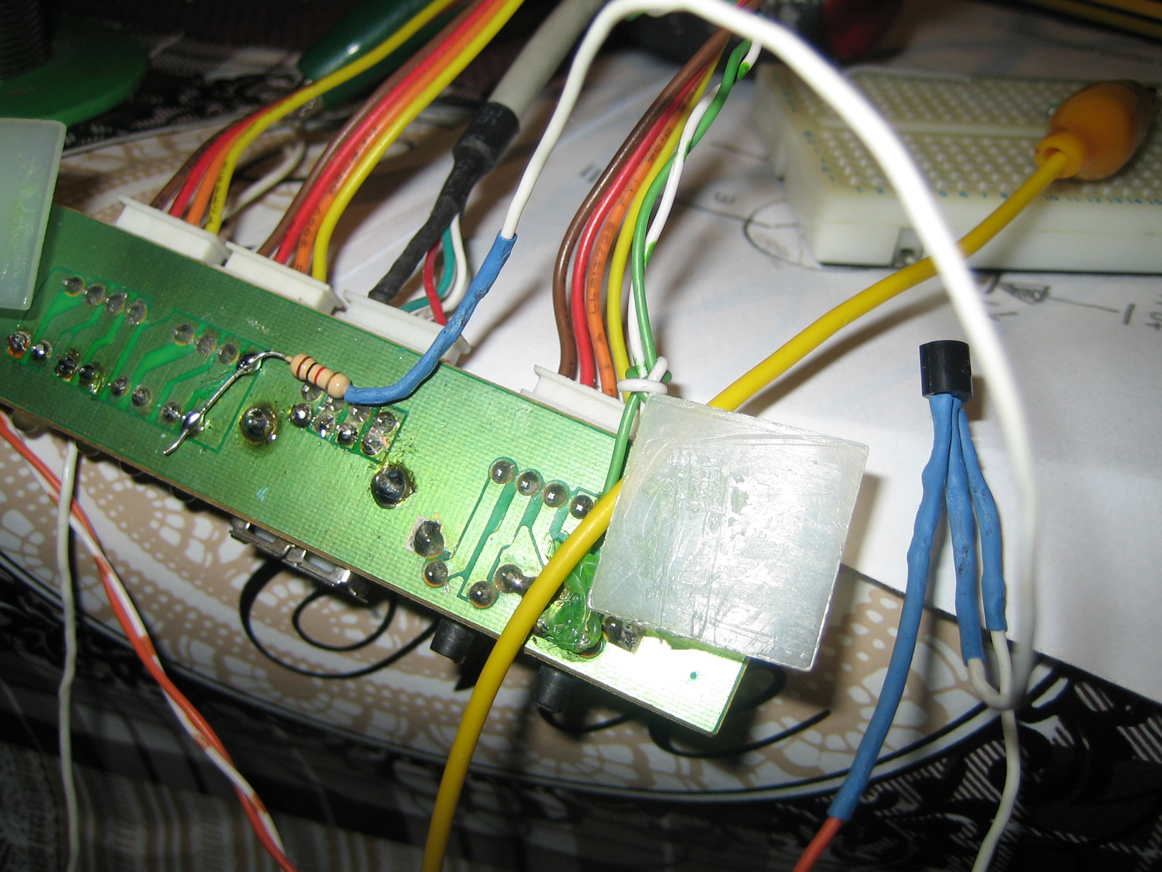
That is it, it now works a treat. I had to wire the positive for the front panel LED to the 5V continuous line on the PSU, as the main power lines shut down when in suspend mode. The original G5 also did the same flashing when suspended, however it instead had a nice fade in/out effect instead of this harsh flashing. Unfortunately that was a PWM signal generated by the Apple motherboard itself, so I would have to make a circuit that approximates that kind of effect. Either way, a project for a future time :-)
That finishes the changes to this project for now. So far I am very happy with it, and I don't expect anything more than minor updates going forward.


